I am new to OpenEMS. For our project as seen in this file we need to implement an ESS with a lithium and redox flow batteries. As stated in the documentation, an ESS is a battery and battery inverter.
Therefore, the simulated ESS doesn’t match my requirements. How would you recommend implementing a redox flow battery and an ESS as stated above?
Additionally, how can I specify the type of the EV Charging Station Connector (AC/DC) in the Apache Felix Console for the Simulator EVCS component?
remaining settings (maxApparentPower, capacity and initialSoc) as required
ESS Cluster (Ess.Cluster)
id: ess0
ess_ids:
ess1
ess2
Simulator EVCS (Simulator.Evcs)
not sure how functional this is…
Then apply a fix Active-Power Set-Point to the simulated ESS-Cluster:
Controller Ess Fix Active Power (Controller.Ess.FixActivePower)
id: ctrlFixActivePower0
ess_id: ess0
power: 10000 (in [W], positive for discharge)
From there you will want to try to optimize how ess1 and ess2 are used in combination and distribute the requested power among each other. You can e.g. put Set-Points to each individual ess via a FixActivePower-Controller (e.g. set 10000 discharge to ess0 and 2000 discharge to ess2 and see what happens). There are different strategies in OpenEMS to decide how to distribute power (->openems/io.openems.edge.ess.core/src/io/openems/edge/ess/core/power/optimizers at develop · OpenEMS/openems · GitHub)
Thank you so much for your feedback and recommendations! I completed my system setup and initial configurations.
Currently, I want to save the simulated data (JSON, CSV formats) and visualize the channels’ values on the History tab in OpenEMS UI. I was looking in the official documentation to solve these issues, but I didn’t find anything that could help me. Do you have any suggestions? If I missed something, please let me know!
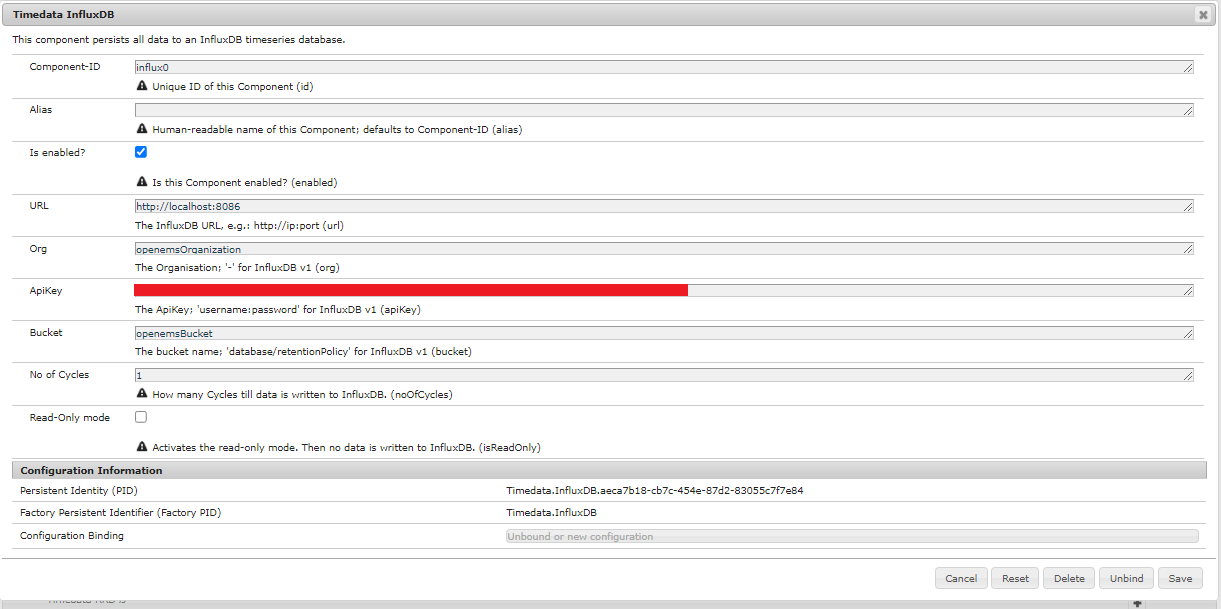
I also tried to store the data in InfluxDB instead, but I wasn’t able to fully understand how to connect OpenEMS with InfluxDB through Telegraf or by using the InfluxDB API services.
Can you please guide me through it? I would appreciate it.
Thank you for your understanding.
Best regards,
Ahmed.
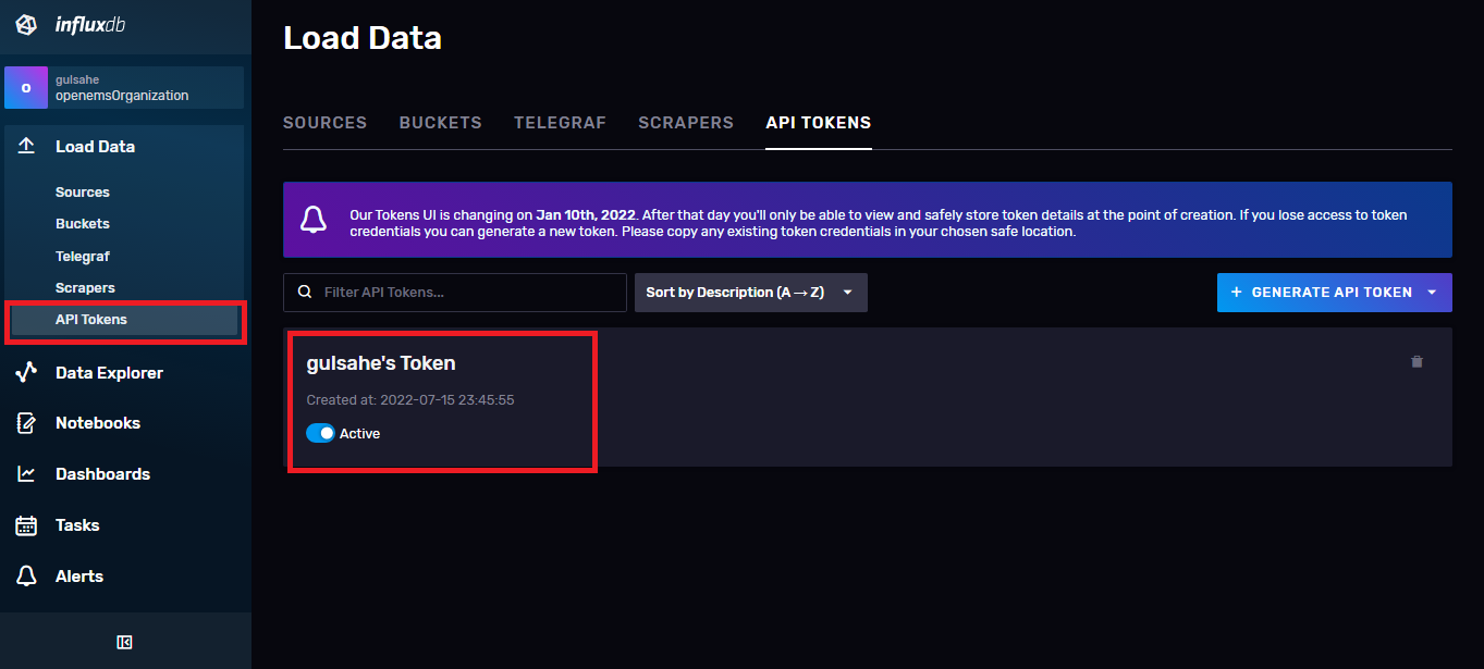
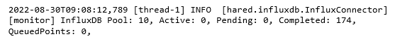
If you are connected you will see influxdb log in your program. Also when you open influxdb you will see your data there. Please see the photos for more detail.
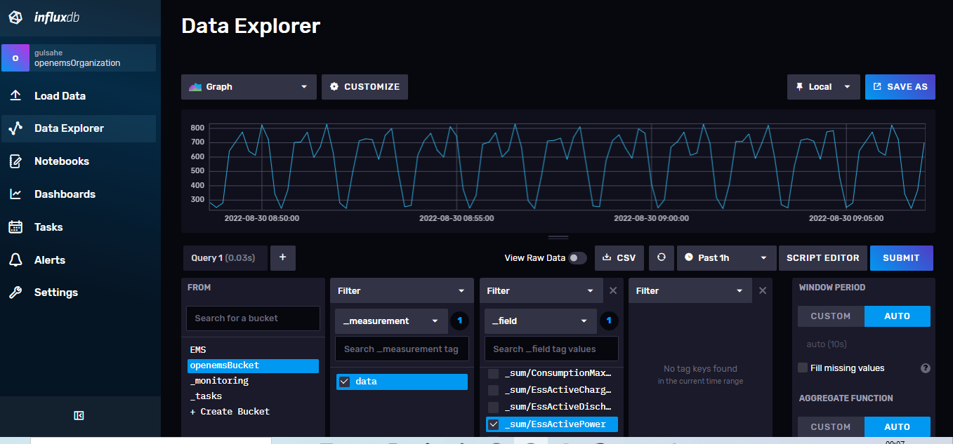
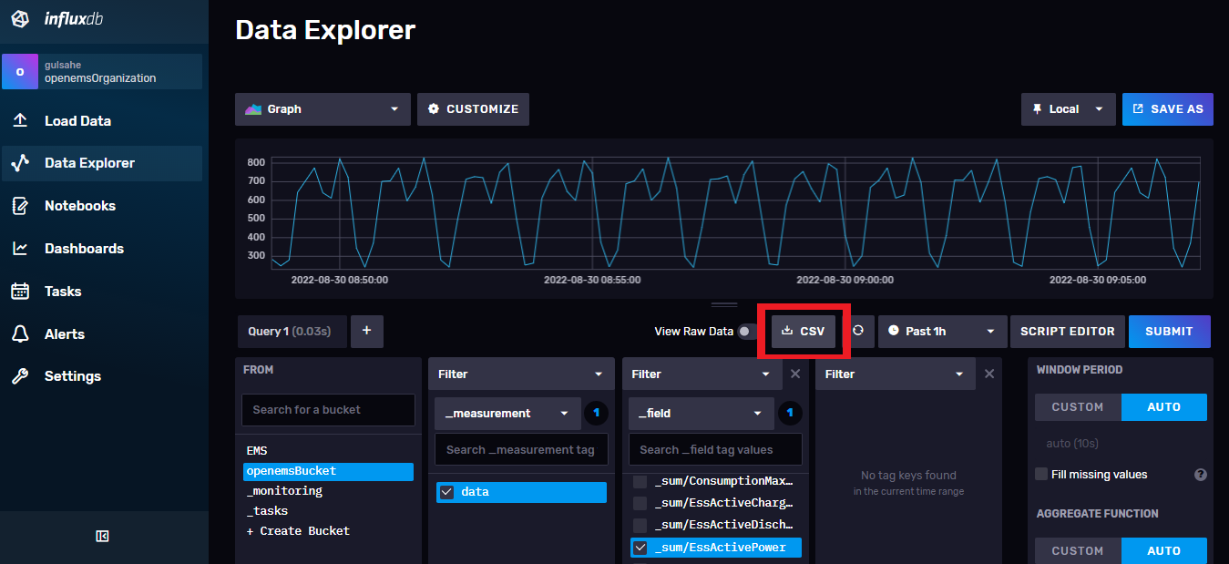
You can save your data in CVS format in influxdb. After calling the data you want in data explorer with a query, you can save the data in the CSV format by pressing the CSV button as it looks in the photo.