I and I am sure many other would like to have DC-microgrid integration within OpenEMS. Examples would be DC consumers, DC-coupled PV, DC-DC converters, DC-link…etc.
Some parts are already integrated, for example DC-Coupled PV (Victron). but the others normally dont have “measurements” so i dont know what you mean by “integrate” dc-dc converters :D. what should happen than?!? to turn them off or on, you have the possibility over relays.
Hi @p.wimmer,
The Hoymiles inverters for example are an interesting Micro-Inverter to Implement for example as they provide Settings aswell.
The “DTU” which is needed is expensive and the only way to control the Inverter (Set Maximum SellToGrid Value etc.)
Also the Hoymiles Inverters have “measurements” ![]()
Another approach (I have it running myself at home) is openDTU. But if it was in openEMS it would be a GREAT step !
Greetings ![]()
Hello,
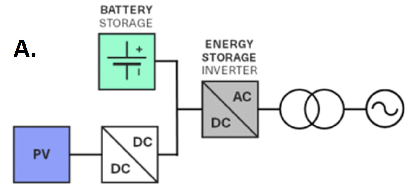
I am also interested in using OpenEMS to support a DC-coupled solar + ESS use case. A schematic representation is shown in the image.
In this case, the solar PV will be potentially fed through a DC-DC converter onto a common DC-bus with the batteries and storage inverter.
I am wondering how OpenEMS could handle this, because the measurement of solar PV production will only be coming from the DC-DC converter.
The particular DC-DC converters we are looking at support measurements and I think it would be not overly challenging to implement an OpenEMS device to support it, however I feel that there would be complexities in terms of how this is represented in OpenEMS UI.
In some ways, the overall situation is similar to a hybrid ESS/inverter where the DC-DC converter and battery inverter together form a virtual hybrid inverter.
I have not yet analysed this deeply but I wonder if a VirtualHybridInverter device could be created that implements the HybridManagedSymmetricBatteryInverter nature and takes references to the ManagedSymmetricBatteryInverter and a DC-DC converter (it would be necessary to create an OpenEMS nature for the DC-DC converter.
I am wondering if I should post this as a new thread but welcome to hear anybody’s thoughts.
I don’t think so as we already have DC-Chargers (see for Example)
If there is a DC-DC Converter with Modbus - easy going ![]()
Ah interesting, thanks for sharing this. I will read some of the code and try to understand it a bit better.
Do you happen to have a screenshot of what the OpenEMS UI would look like with such a DC-charger in place?

Thank you.
And the Solar PV production is the sum of the output of the DC chargers? Is that right?
I can see in the visualisation the solar PV production of 0.2 kW which appears to be the sum of the power from Hausdach Links and Rechts… is that right?
I have found such a DC-DC converter/charger that supports Modbus-TCP so I think it should be simple enough to implement when the time comes.
Thomas
In my Case i have:
2x DC Charger
2x AC - Production meter
but in general the 0,2kW Displayed is the sum of all of them, yes !
Would be glad to help if you need something ![]()
Thank you!
Just to be clear then, if I want to implement a DC charger which acts as a DC-DC converter and charges the batteries from the solar, I guess I should use the EssDcCharger nature in OpenEMS?
I.e if I was implementing a device which takes the place of the DCDC converter in my diagram above? I.e takes the solar PV production and injects it on the common bus with the battery and inverter.
yes indeed should work