How many devices can OpenEMS Edge handle/control/monitor?
Specifically, if most devices use Modbus. Note that they are different (batteries, inverters, chargers, etc., and not necessarily the same brand/model).
How do I determine the number?
I am currently using a Raspberry Pi 4 controller for the OpenEMS Edge with a 1.5 GHz quad-core CPU and Debian 13.2.0 64-bit.
there is no easy answer on this. In general I think the Modbus Implementation of OpenEMS is the most advanced and stable Modbus implementation I can imagine. I think there is no practical limit on the number of devices you want to control/monitor. You can create as much connections to as much devices at the same time.
But it depends on your expected response times and on the concrete driver you are using. And of course you have technical limits like the interface (Modbus RTU, Modbus TCP/IP).
To give you a few examples from practive, we have
a system with 35 PV inverters (different models) or
another system controling 50+ charging stations plus a few meters or
another one monitoring 30 electricity meters.
In all cases we have cycle times of 1s and the CPU usage is less than 10% (on a Raspberry Compute Module 4, no dynamic tariffs, no predictions…).
But we also have a pilot system controlling only 3 KACO battery inverters and deeply monitoring the battery stacks. This system has a cycle time of 2.7s , because we are not able to communicate to all devices within 1s (Note that this is based on an old OpenEMS version, the Modbus implementation had major improvements since then, so today I would expect to handle it a bit faster).
So if you want to monitor a lot of electricity meters with a cylce time of e.g. 5min (UseCase Mieterstrom) you may add a thousand electricity meters easily. If you want to control a battery doing high speed electricity trading within 200ms cycle time, you may just be able to control only one (optimized) meter and only one (optimized) battery inverter.
Thanks a lot! That is very insightful and helpful!
What do you think of the case when you have assets (batteries, inverters, charging stations (AC + DC), grid connection, and HVAC), mostly communicating through Modbus, and a few OpenEMS Edge optimization and regulation controllers (e.g., peak shaving and §14a German regulation)?
Would there be any limits or issues with them (for Raspberry Pi CM4)?
Did you define the cycle time while configuring OpenEMS or while designing (did you estimate the cycle time for each device), or was it set automatically based on the process’s time consumption? Can it be set dynamically based on the real-time execution events?
In general I would say no problem. But as mentioned, it depends greatly on the specific devices, the specific implementation, and the specific use case. It is like shown here:
we typically run a cycle time of 1s, which fits to most of the cases very well.
try to use an ESS, which has low response times. Best is if you can get reaction times < 1s. And try to use an ESS, which do not add any delay or PID filter on it. It is best to add PID from within OpenEMS.
I would try to start with only one ESS, because you probably need a lot of time to understand the mechanisms, when using multiple ESS (especially the ESS Power object).
up to 5 or 10 PV inverters should not be a problem.
the EVCS Cluster has peculiarities. Right now it best works with Keba charging stations. And you may add maybe 5 EVCS. It will be replaced by the new EVSE architecture, which should become way more stable even with other charging station models. In your case I would probably already start with the EVSE implementations.
2 or 3 HVAC should not be a problem
peak shaving is not a problem, but understand that this is not a real time peak shaving. It does peak shaving on a 15min base. Depending on your ESS reaction times and your configuration your peak will be exceeded for a few seconds from time to time. Your peak limit should stay far away from the grid fuse limit. Also be aware that the general peak shaving controller does not take care of phase imbalances.
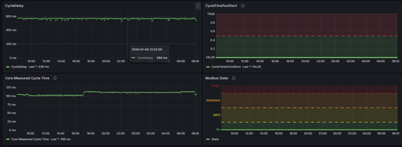
When system is up and running you can check some special OpenEMS channels to understand your system performance better. We have build up a grafana dashboard to check performance issues. Here you see an example of the modbus communication to an ESS:
modbusX/CycleDelay - the time the modbus component is sleeping during a cycle.
modbusX/CycleTimeIsTooShort - flag is raised if the communication to a device can not be done within the current cycle time.
_cycle/MeasuredCycleTime - the time OpenEMS needs for running a complete cylce.
This screentshot is from a system with 750ms cycle time. It indicates a stable system, as it has no artefacts and no outliers. System is more or less idle. So we could increase the cycle time if we want.
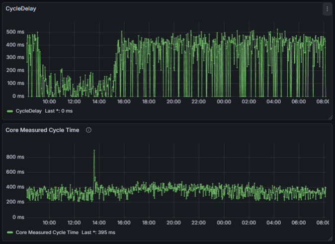
And here you see a totally stressed system:
I truly appreciate all of the helpful information and advice.
Now that I have a better understanding of the matter, I will go ahead and start with some simulations using the simulation tools on OpenEMS, then integrate hardware one by one.
I will consider debugging/performance measurement tools afterwards for system optimization purposes.
In my case, I will be working on already-existing assets (ESS, PV inverters, etc.); however, for new system installations, I will recommend assets based on what you suggested.
I might get back to you if any other concerns arise.