OpenEMS Simulation Configuration Steps
This guide provides step-by-step instructions for setting up and debugging OpenEMS simulations.
Step 1: Simulator App
- Action:
- Check
enable. - Click
save.
- Check
- Notes:
- This will clear all existing configurations. Ensure no critical data is lost before proceeding.
- After clearing, all essential settings must be reconfigured in sequence.
Step 2: Scheduler (All Alphabetically)
- Settings:
ComponentID: scheduler0- Check
enable. - Click
save.
- Functionality:
- Automatically starts the following core components in alphabetical order:
coreess powerevcs powerController Api Websocketlog
- No additional configuration required to ensure basic system functionality.
- Automatically starts the following core components in alphabetical order:
Step 3: Controller Debug Log
- Settings:
ComponentID: ctrlDebugLog0- Check
enableandCondensed output.
- Functionality:
- Enables debugging mode with condensed logs for troubleshooting and system analysis.
Step 4: Simulator DataSource (CSV Predefined)
Configure three data sources to simulate load, PV generation, and ESS data.
-
Load Meter Data Source:
ComponentID: datasource0- Configuration:
- Check
enable. Factor: 10000Time-Delta: -1Source: h0-summer-weekday-standard-load-profile.csv
- Check
-
PV Meter Data Source:
ComponentID: datasource1- Configuration:
- Check
enable. Factor: 10000Time-Delta: -1Source: h0-summer-weekday-pv-production.csvorproduction2.
- Check
-
ESS Data Source:
ComponentID: datasource2- Configuration:
- Check
enable. Factor: 10000Time-Delta: -1Source: h0-summer-weekday-pv-production2.csv.
- Check
Step 5: Simulator GridMeter Acting
- Settings:
ComponentID: gridmeter0- Check
enable.
- Functionality:
- Simulates grid monitoring, providing data on grid power, state, and flow direction.
Step 6: Simulator EssSinglePhase Reacting
- Settings:
ComponentID: ess0Phase: L1(single-phase setup; use L2 for two-way or L3 for three-phase setups).Datasource-ID: datasource2Max Apparent Power [VA]: 10000Capacity [Wh]: 10000Initial State of Charge [%]: 30Grid mode: On_Grid(enables grid interaction).
- Functionality:
- Activates a single-phase ESS to simulate power response.
Step 7: Controller Ess Balancing
- Settings:
ComponentID: ctrlBalancing0- Configuration:
Energy System ID: ess0(matches Step 6).Grid Meter ID: gridmeter0(matches Step 5).Target Grid Setpoint: 10.
- Functionality:
- Controls ESS and grid meter to maintain balanced power flow.
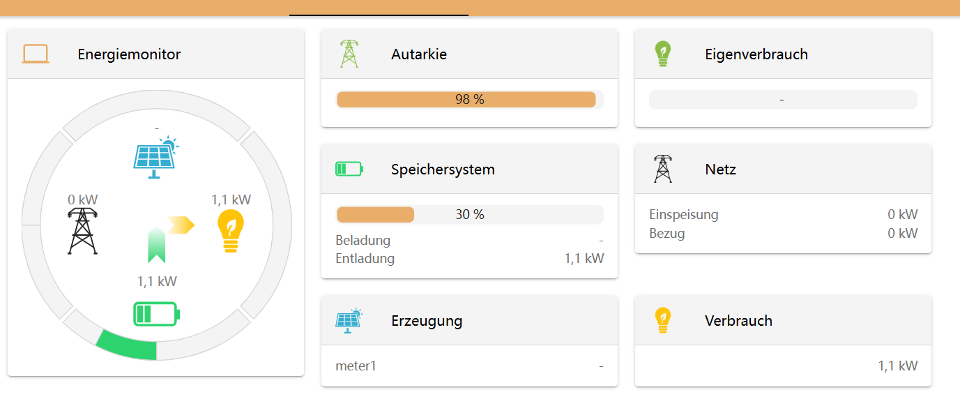
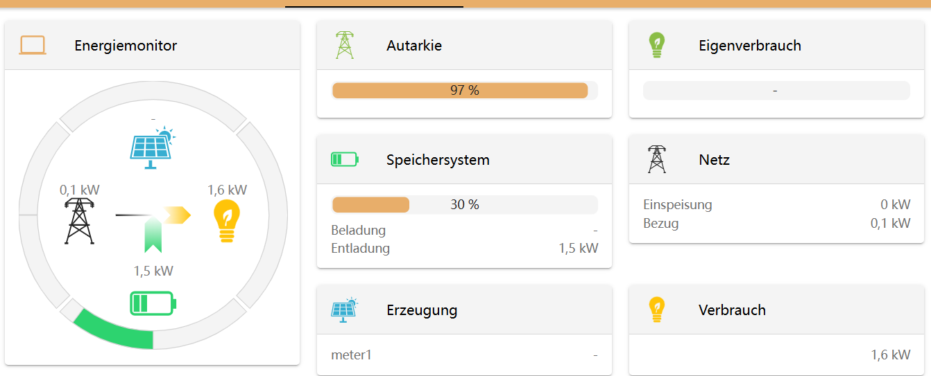
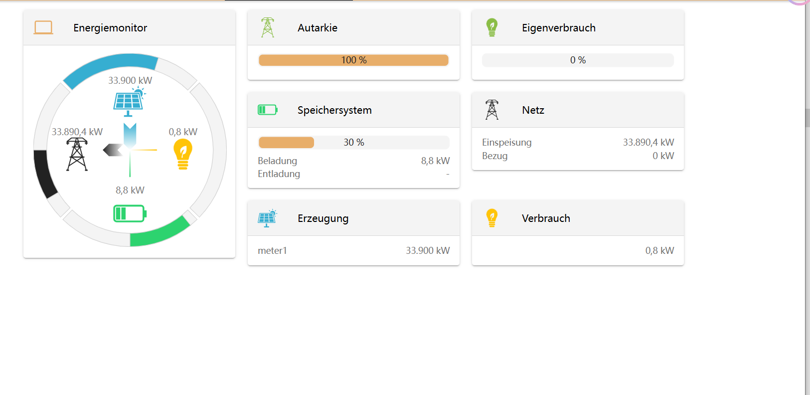
Step 8: Controller Api Websocket
- Check:
- Ensure WebSocket is enabled.
- Functionality:
- Facilitates communication between OpenEMS and the UI.
- The UI will not display system status if WebSocket is disabled.
Step 9: Simulator Battery
- Settings:
ComponentID: bms0- Check
enable. - Configure parameters:
Number of slaves: 1Discharge min voltage: 44Charge max voltage: 56Discharge max current: 50Charge max current: 50SOC: 75SOH: 95Temperature: 30Capacity KWh: 50Voltage: 5Min cell voltage mv: 3300.
- Functionality:
- Activates the battery simulator with customizable parameters.
Step 10: Simulator NRCMeter Acting
- Settings:
ComponentID: meter0- Check
enable. - Configuration:
Datasource-ID: datasource0.
- Functionality:
- Activates load meter simulation, linked to
datasource0.
- Activates load meter simulation, linked to
Step 11: Simulator Production Meter Acting
- Settings:
ComponentID: meter1- Check
enable. - Configuration:
Datasource-ID: datasource1.
- Functionality:
- Activates PV meter simulation, linked to
datasource1.
- Activates PV meter simulation, linked to
Additional Recommendations
-
Step-by-Step Validation:
- Save after adding or modifying each component.
- Use the OpenEMS WebSocket interface to verify component statuses incrementally.
-
Log Monitoring:
- Enable debug logs (Step 3) for detailed analysis of system interactions.
-
Simulation Flexibility:
- Adjust parameters like battery capacity, power limits, and load curves to better simulate real scenarios.
-
Advanced Features:
- Use custom data sources or scripts for extended simulation, e.g.:
- EV charging load simulations.
- Fault condition testing (e.g., disconnections, overload).
- Use custom data sources or scripts for extended simulation, e.g.:
By completing the above steps, the simulation system will be ready for testing and validation of complex scenarios.